Tuesday, February 14, 2012

The Arduino Learner's Project - Part II

The Rehash
In my previous blog post I explained the trials of simply starting the project and how I came about to creating my list of high level requirements. The requirements follow. As you can see, some have been crossed out since some purchases have been made.
  • microcontroller (uC) with enough ports
  • LCD for human interface
  • keypad for human interface
  • Real Time Clock (RTC)
  • power supply (and transformer)
  • wireless interface of some type
  • method for controlling irrigation solenoids
  • humidity & temperature sensor(s)
  • moisture sensor(s)
  • and eventually a nice case of some type
Since I already had purchased a 16x2 LCD arduino shield and picked my arduino (atmega2560), I had my first three items addressed. Remember, most LCD shields come with micro switches which serve as buttons, allowing for human interaction. And so these items are crossed off our list above.


Sprinkler Basics
Irrigation systems are broken into multiple zones. Each zone is sized based on the water pressure in an area. Each sprinkler head requires a fixed amount of pressure. So given a fixed amount of water pressure, each zone is broken into a given number of heads. Each zone, in turn, is controlled by a valve.

Basically the way a sprinkler controller works is by triggering a relay or triac to open or close a solenoid which opens or closes a valve. The valve in turn allows water to flow into the zone and out the sprinkler heads. Most residential solenoids require roughly 150-300mA of current while in operation. Because of water pressure constraints, normally no more than two valves (one zone) will be open at one time. By extension, no more than two solenoids need be active at one time. Though only one valve need actually be used, commonly two are used in conjunction with each other. The determining factor for one or two is based on your irrigation installation. Typically one solenoid is used per zone and optionally a master solenoid is used at the head of the system. So long as the irrigation system is running, the master value plus another for a specifically enabled zone, is active.

Some irrigation systems do no have a master valve. Others do. For some systems, the master valve is used to not only open a valve, but also to turn on a primary pump (e.g. well water) and/or boost water pump (low water pressure and/or over sized zones). Please keep in mind I'm speaking generalities here. I'm aware there are exceptions. Please verify your own installation requirements before assuming the details here are valid for you system.

As I'm using a relay board, my relay(s) holding current also needs to be added to the sum current required for operation. On my relay board, each relay requires 80mA while in operation. To keep two valves open requires a worst case of (300+300+80+80) 760mA of current. Once we add in the load for the uC, LCD display, radio interface, and inefficiency losses though our regulator, we'll be pretty close to our maximum of 1A. It may turn out I require a larger transformer, but for now, 1A (1000mA) remains my target. Worst case, I already have my eye on a refurbished 1.5A transformer for not a lot of bucks.


The Ultimate Power Source
There are many different directions to look at here but ultimately I decided to re-use the power supply of my existing sprinkler controller. This has the advantage in that it has the power required to directly drive the sprinkler solenoids without incurring additional cost.  This meant I still needed another power supply to drive the microcontroller (uC) side of things. The catch is the transformer's input is 120VAC and output is 1A@26.7VAC. I need 5VDC for my uC, display, and relays. So clearly I need to convert 26.7VAC to 5VDC.

After some asking around, most people pointed me at something like this, which provides for high efficiency switching regulation and minimal part count; which still requires several anti-ripple capacitors. After learning more about AC to DC conversion, I figured out its too small. This is because the peak-to-peak conversion will yield roughly 36VDC after basic rectification. What I really needed was something like this. Which means we just jumped from a $16.25 solution to a $26.50 solution, and I still needed my own front end circuitry to rectify AC into DC. That dog won't hunt as powering the device would become one of the single most expensive components of my build. Heresy I say, as it violates my frugal nature. And so I decided to keep looking. This is when I discovered devices based on the LM7805; switching regulators. That's more like it. After shipping its basically $10. Certainly looks like a good buy and it received a thumbs up from those who previously pointed me at the more expensive counterparts.

I then hit ebay and started looking for LM7805 based solutions. That's when I stumbled on LM2596 switching regulator based solutions. For cheap, roughly $3.00 or less, including shipping, you can get a variable output switching regulator. These typically accept up to 40VDC as input and can output up to 3A, so its perfect; even if I need to upgrade my transformer at a later date. Of course, this still requires rectification on the front end; but so did the higher priced solutions above. The disadvantage of this solution is that its larger. But even that is a little misleading as they all required several capacitors; two minimum, three recommended. The ebay solution has all that already included in its foot print.

If you need a tiny footprint, don't care about cost, or simply don't want to wait on the proverbial slow boat from China (or HK), I'm sure you'll be happy with one of the solutions above. If on the other hand, you're looking for a cheap solution, footprint doesn't matter, or delivery schedule isn't a first order concern, head to ebay. I guess time will tell if it turns out to be a frugal or foolish purchase. Having said that, I did find other frugal hobbyists who have found ample satisfaction with these low cost devices. That said, its not clear they are all equal.

Please note all of these solutions use a switching regulator for DC to DC regulation (often 85%-93% efficient). None of the above are linear regulators. For my project, this is very important as the conversion efficiency is typically much lower for the linear regulators (75%-85% efficient). In my case, would have also required a large heat sink to dissipate the heat from the inefficient conversion. Linear regulators do best when the voltage delta is small. In my case, the voltage difference is relatively very large, which results in a lot of current being converted to heat. Given my voltage spread is ~31 volts, and I only have 1A available on my transformer, and as you can see above we're already tight, I didn't consider it an acceptable loss.


Rectifying The Situation
The last part of our power source is a bridge rectifier. This is an incredibly simple circuit. It can be built with four diodes or as a single integrated package. Basically this converts the sinusoidal wave of AC input into a heavily rippled DC output.

Basically it converts the top sine wave...

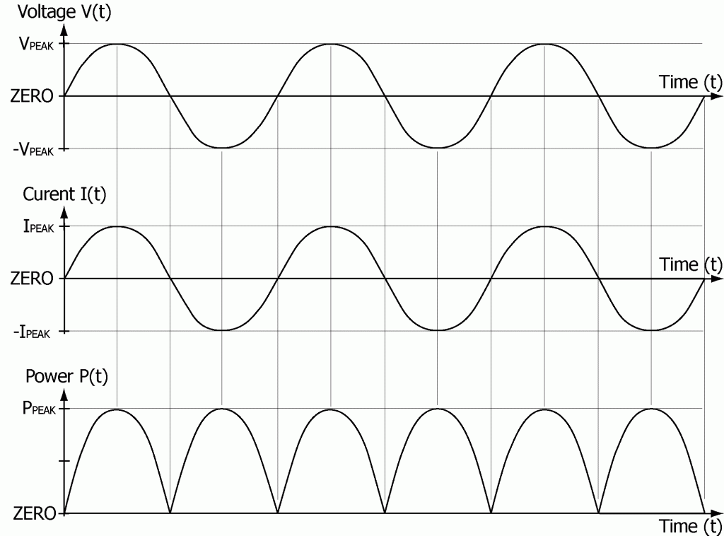
...into the rippled DC wave at the bottom. I still have not decided if I'll use a bridge rectifier or make one out of diodes. In the short term I did go ahead and build a diode bridge and tested it. Super simple and easy to make. But having done so, it makes you realize how much of a foot print it requires so I certainly understand and appreciate the appeal of a smaller IC, which serves the same purpose. We'll see.

What we wind up with is a complete power supply for roughly $3.00USD, including some diodes for rectification and even some capacitors, should it turn out they are required.


The Driver
From what I've found and have been told, triacs are more commonly used for commercial controllers. But to keep things simple, I'm using a relay board, which is just a collection of relays on a board. In my case, the board is also optically isolated which means I don't need to worry about 26.7VAC ever jumping into my sensitive 5V circuitry. While triacs are typically lower current draw than relays, in my case, I believe a pre-built relay board just nicely simplifies things.

Relays do have a disadvantage beyond higher current draw, in that they are a mechanical device. As relays are an electromechanical device they do wear out with repeated use. But given the usage patterns associated with an irrigation system, I believe my choice of board will easily provide a lifetime of use. After all, if you water twice per day, three times per week, four months out of the year, you wind up with 96-cycles per year. Even if this is grossly under estimating, these relays should be good for hundreds of thousands of cycles so we should still have a lifetime of use. And even if one does fail, the relays are easy to find online and large enough for someone with bad eyes to replace them as needed.

Speaking for relay failures, should a relay fail in the open condition, since my system does have a master relay, I'm still protected. Basically my system will require the failure of two relays before I need worry about my yard becoming flooded, should it fail in the open position.


Episode Summary
So far we have selected our uC, user interface, and decided how we plan on powering everything. Next we'll start looking at our radio solution which turns into a tangent project in of itself.

Wednesday, January 18, 2012

The Arduino Learner's Project - Part I

Inception
I had originally considered this project many years ago while working for a hardware manufacturing company. And so I went about asking about details required for my project as hardware engineers were plentiful. I had heard rumblings of Arduino but really didn't know anything about it and I certainly hadn't explored any details. And so I trusted the answers I heard. After all, this is what he does for a living. The answers meant the project was cost prohibitive so I simply let the project go there - but not forgotten. I was disappointed to say the least.

Years later I learned the information provided by my learned professional was more or less, completely wrong. I don't know what he had based his information on but it turns out it can be done for a fraction of the cost I had been told and certainly by using more frugal methods than had been suggested or what I had originally considered. I realized all this after curiosity got the better of me and I started exploring the Arduino platform.

Long story short, creating your project is likely easier and more cost effective than you think.


The [Advanced] Wireless Sprinkler Controller
The project at inception was originally going to be a cheap Buffalo wireless router with some relays and custom Linux code. Once I started seriously looking at an Arduino solution, I realized it could be much cheaper yet. It was at this point I started learning about sprinkler system controllers, their defacto solenoids, and the voltage/current requirements. And so I started looking for various components to piecemeal my project.

I realized early on I wanted more than just another sprinkler timer. If you check, you'll find many such Arduino based projects. Some even complete with code and schematics. None of these really scratch my itch as they are typically a generic scheduler and timer and/or the former plus a web interface. All more or less variations of a theme. None of which are terribly exciting for me.

Well, I wanted none of that. I already have a nice multi-zone sprinkler controller and timer. Adding a web interface is slick but doesn't really do anything aside from save me a trip to the garage a couple times per year, plus timer adjustments after I realize the grass is getting burned. Not really sexy enough. That's when I realized I wanted a smart controller. Some investigation reveals the level of smarts I want is retail priced in the $600-$1200 dollar range depending on the specifics and brand of controller. Now that sounds like a project. While I don't expect exact feature parity with these costly commercial offerings, I do believe I can get mostly there for a fraction of the cost.

You might be wondering what this does that the others don't. Well, for starters, they automatically adjust water based on an array of environmental factors. Generally speaking, the person behind the controller provides operational criteria for each zone and the controller does the rest. This means, for example, no watering while its raining and extra watering during those triple digit heat waves, all without any input from me. What this really means is the opportunity to play with lots of different sensors and embedded development while creating something practical at frugal expense.


The Arduino Platform
There is a lot of confusion about what Arduino actually is. It doesn't help that the group behind Arduino seems to take pride in obfuscating what Arduino actually is.

Arduino is a Microcontroller (uC), a USB interface, (typically) power regulators (3.3v and 5v), any number of microcontroller pins pulled out to easily accessible headers, a bootloader, a set of high level libraries (which come at a performance cost), and a primitive IDE.

The USB interface provides a means of powering the board and small, attached devices, as well as a means for basic input and output (I/O). This means of I/O is also the basis for flashing (sending your program to) the microcontroller. This interface also alleviates the need to have a separate device known as an In Circuit Serial Programmer (ICSP); though headers are typically broken out to allow for easy attachment of an ICSP to the board. Its important to understand, this interface does not actually extend USB access to the Arduino platform as the available USB interface is completely abstracted away (and frequently controlled by a second on-board microcontroller or USB TTL chip) so as to look and act like a serial port.

Next is the language. Its extremely annoying they call programs, "scripts", when in fact, they are absolutely are not. "Scripts" are typically associated with a scripting language and none of the languages supported by Arduino qualify as a scripting language. You program Arduino in C, C++, and Atmel AVR assembler. The standard Arduino library does, however, do a good job of simplifying some of the more involved tasks associated with embedded development. So don't let the newly revealed truth scare you away.

In a nutshell, Arduino is a rapid prototyping and development platform. And the best thing is, you need not actually deploy your project with an Arduino. You can build a system using the minimal components required, thusly helping to reduce deployment costs. Meaning you can use Arduino strictly for development and deploy with a much lower cost solution; frequently for a couple of bucks plus any external devices and sensors. Of course, to do this requires some extra hardware expertise. But if you, like me, are lacking this expertise, visit the Arduino Forums. You'll find you're not alone and that lots of help from a very active and friendly community is ready to assist so long as you're willing to put in the effort.


Arduino Selection
Once anyone starts looking at the full spectrum of official and unofficial Arduino hardware, board selection can become somewhat daunting. Doubly so when you have no idea what your code and pin count requirements will be. Since I was new to Arduino I decided I would err on the side of caution and simply get a big Arduino with the understanding I can always step down in a variety of way. After all, this is in large part, Arduino's claim to fame as Atmel makes a large selection of arduino compatible 8-bit microcontrollers.

I quickly settled on a Mega 2560. The specifications show it to be a fairly robust 8-bit microcontroller (uC) and so it seems like a very sane board into which I can grow. Sadly, experience has taught me otherwise. In fact, for a general purpose development board, especially for a beginner, I can not recommend strongly enough you stay away from this board. The board is very poorly supported, making it the exception rather than the rule. Reportedly it has a minor and rarely observed hardware bug which can require physical reset to recover. Worse, the bootloader has a critical bug such that the WDT can not be used. And even more frustrating, simply flashing code which contains the character sequence of, '!!!', will cause the flash to fail. Made even more frustrating, that sequence can be generated by the compiler, so flashing your code can suddenly just start failing without any indication as to why. Also, there is an issue where the EEPROM can't be programmed when its flashed, meaning your program must always setup initial state. There is also an issue accessing all of the 2560's memory in many circumstances. In the Arduino world, its by far the odd man out.

It also turns out the physical form factor is at a disadvantage for two reasons. These boards are not compatible with all Arduino Shields. The second physical issue is that the uC is not socketed. This means if you burn out a pin on the uC, that's that. In contrast to most other Arduinos, they are much more forgiving because you can simply replace the socketed uC for a couple of bucks and lesson learned. Whereas, with the Mega 2560, you need to lay down another ~$55 bucks or so. Costly lesson.

Compiler support is another real hit or miss issue with the Mega2560 and various Linux distributions. Turns out my then Linux distribution, Mandriva, happily provides an extremely buggy compiler. It was so bad, many of the Arduino examples would simply fail to run. I wound up having to compile my own gcc tool suite and avr-libc, which proved to be another project in its own right. And I can assure you, that's the very, very terse version of it. Eventually with the help of others on the Arduino and AVR forums, I was able to create a working environment. Sadly, Mandriva is far, far from alone here. I guess the good news is, if you run Windows, the Arduino environment is very well maintained so Windows users need not fear. If you're a Linux user, do not trust the AVR compilers out of the box unless you know for a fact it works with your uC of choice.

All of these issues are known for well over a year or more at this point and there seems to be little incentive for the developers to support this hardware. So in a nutshell, unless you are absolutely positive you need the Arduino Mega 2560, avoid it at all costs. If you still want a high end Arduino, consider the Arduino Mega in its place. It doesn't address the socketed uC issue but it also doesn't have all the other bugs.


"The Controller"
 or
"One Controller To Rule Them All"
To pull this project together, we need a number of different components and sensors. So the generic and very rough list looks something like this:
  • microcontroller (uC) with enough ports
  • LCD for human interface
  • keypad for human interface
  • Real Time Clock (RTC)
  • power supply
  • wireless interface of some type
  • method for controlling irrigation solenoids
  • humidity & temperature sensor(s)
  • moisture sensor(s)
  • and eventually a nice case of some type
The uC needs to have storage to hold a program large enough to meaningfully handle LCD output, keypad input of some type, a wireless interface and associated protocol, read various sensors, and enough computing power to perform some type of environmental simulation to keep my lazy self out of the garage. It also needs to have enough EEPROM storage to maintain its configuration when power is out.

Notice the wireless component of the project keeps popping up. The wireless component exists to optionally enhance environment information, allow for configuration of zones, and to obtain logged irrigation zone information (when, how long, sensor readings, etc). And of course, to not be left in the dark with more traditional Arduino sprinkler projects, the wireless component is to allow for manual operation of each zone as well as simple timers.

Stay tuned to see how this progresses.